Ventilation unit Vast1
The body of the Vast-1 ventilation unit consists of an aluminum frame, fastened together with strong plastic corners. The panels are attached to the body through a seal. The panels are made of galvanized steel as standard, but can be made of stainless steel of various grades and degrees of surface gloss. It is also possible to paint the panels in RAL colors. Inside, the panels are filled with a layer of mineral wool based on basalt group rocks with a density of 50 kg/m3.
The units of the Vast-1 ventilation unit are installed on 100mm high galvanized steel support legs; if desired, the units can be installed on adjustable legs.
Blocks
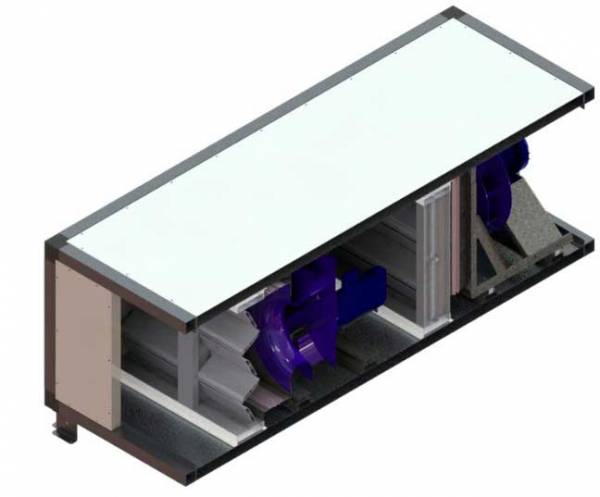
The fan unit is designed for use in supply and exhaust systems. The fan is based on a ventilation unit and is a mechanical device designed to move clean and dry air through the air ducts of air conditioning and ventilation systems and creates the necessary pressure drop (at the fan outlet and inlet). The fan group consists of an impeller and an electric motor. This group is attached to the frame, which in turn is attached to the body through rubber vibration isolators. It is possible to perform with backup of the electric motor, as well as with backup of the entire fan.
Upon request, thermal protection can be built into the motor windings.
1. Water heater block
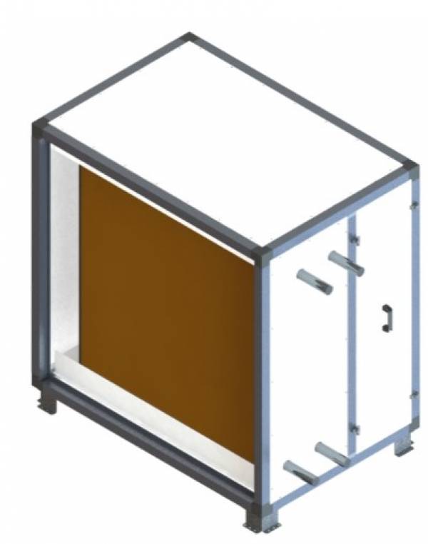
The water air heater unit is designed to heat the air by transferring heat from water or an antifreeze mixture passing through its tubes.
These heaters belong to the class of copper-aluminum plate heat exchangers.
The body of the heaters of this type is made of galvanized steel.
Maximum permissible pressure during testing: 1.6 MPa (16 kgf/cm2).
Maximum permissible coolant temperature: 150C.
2. Electric heater block
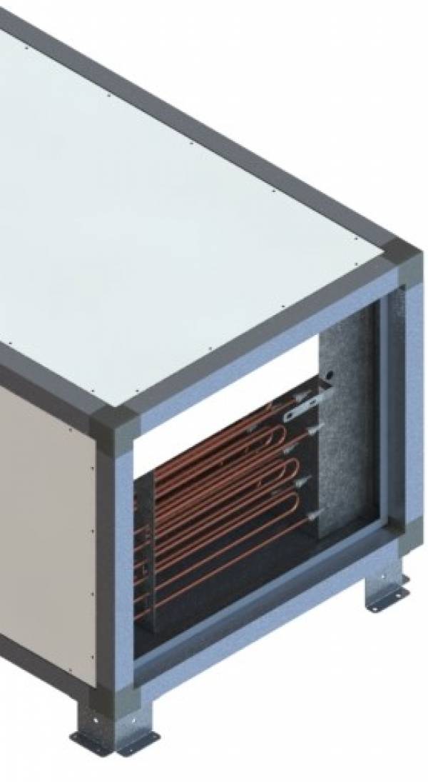
The electric heater block is used as the main air heater in supply ventilation systems, as well as pre-heater in ventilation units.
Air temperature before the heater: no more than +25C.
Maximum permissible outlet temperature: +50C.
The electric heater unit consists of a housing and an air heater. The heaters are made of stainless steel heating elements of increased reliability. The junction box contains the necessary terminals for electrical connections, with clamps for simple and quick installation. The air heater is designed to operate in a three-phase or single-phase (depending on the model) alternating current network with a frequency of 50 Hz.
3. Freon/water cooler unit
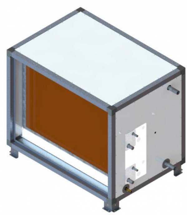
The freon air cooler unit is designed to cool the air by transferring heat to the freon passing through its tubes.
The air cooler section consists of a housing, a heat exchanger, a drip separator unit and a condensate collection tray. The cooler heat exchangers belong to the class of copper-aluminum plate heat exchangers. That is, the heat exchanger tubes are copper, and the plates that increase the area of the heat exchanger are made of aluminum. The housing is made of galvanized steel. The drip separator unit is made of a 100 mm wide plastic profile cut into strips and installed every 33 mm along the entire length of the heat exchanger. The plastic profile has special bends that trap moisture droplets. Condensate is removed through a branch pipe in the lower part with a diameter of 21.3 mm. The maximum allowable working pressure is 1.6 MPa.
The connection of the pipes to the refrigerant network is carried out through a threaded connection for water coolers or by soldering for freon coolers.
The cooler section must be installed horizontally with the condensate collection tray facing down. To operate the cooler, it must be connected to the compressor-condenser unit.
4. Recuperator block
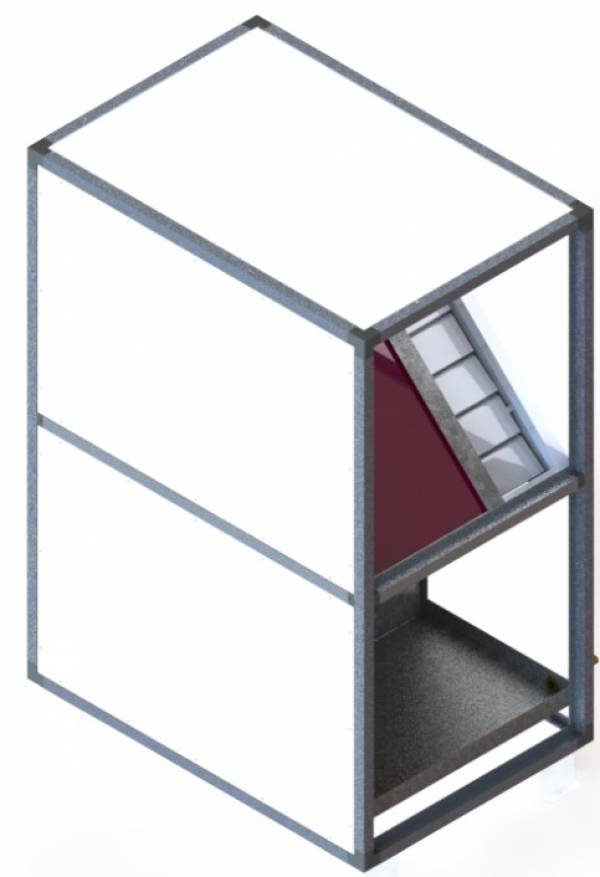
The recuperation unit is designed to return the outgoing heat from the unit back. Plate, rotary and glycol heat exchangers (heat exchangers with an intermediate coolant) are used as regenerators. Plate recuperators are cross-flow heat exchangers used for heat recovery (return) in building ventilation systems. These recuperators allow energy savings in ventilation and air conditioning systems of up to 70%.
The principle of operation of a plate heat exchanger is to transfer heat from the exhaust air to the supply air. Warm exhaust air (from the room) and cold supply air (from the street) pass next to each other and without touching, transfer their energy along the surface of the plate. In this case, there is practically no mixing. Due to this, moisture, odors and contaminants from the exhaust air are excluded from entering the room.
To increase efficiency and obtain the best aerodynamic characteristics, the channels of plate recuperators are made of a special shape and structure. The plates of the recuperators are made of aluminum and are firmly connected using double folding, due to which the design of the recuperators is maximally stable. The large thickness of the aluminum plates allows the recuperators to operate stably even in conditions of high humidity, while maintaining the maximum lightness of the structure. Also, due to the large thickness of the material in the recuperators, excellent pressure stability is ensured.
The section of the plate recuperator unit consists of a housing, a tray and the recuperator insert itself, and can be equipped with a drip separator in the exhaust section upon request. A drainage tray is provided in the recuperator design to dispose of condensate that occurs during energy transfer. The outlet for condensate drainage is located at the lowest point of the recuperator housing. As standard, the plate recuperator section is equipped with a bypass damper with a drive (smooth control).
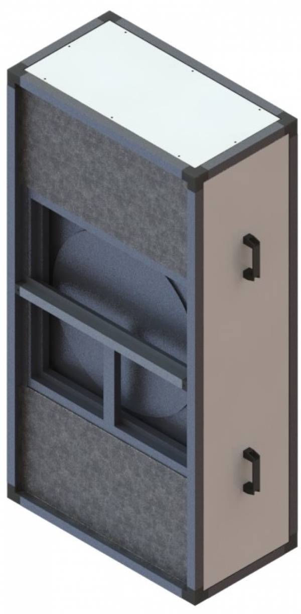
Rotary recuperators are rotary heat exchangers used for heat recovery. This type of heat exchanger is considered the most energy-efficient (efficiency up to 80%).
The principle of operation of the rotary recuperator is to transfer heat by rotating the wheel. Warm exhaust air heats the plates, then these plates rotate and in turn heat the cold supply air. The disadvantage of these recuperators is a small flow of exhaust air. The advantage of this regenerator, in addition to high efficiency, is the return of moisture to the supply duct. The section of the rotary recuperator block consists of a housing, a wheel, a belt drive, a motor and a frequency regulator. When calculating supply units in a composition with a rotary recuperator, it is advisable to provide empty sections before and after the rotor in the exhaust and supply duct. These sections allow for more convenient maintenance, inspection and cleaning of the rotary recuperator.
Recuperators with intermediate heat carrier are recuperators mounted in supply and exhaust ventilation units, which are located in rooms with high requirements for air purity and quality. Recuperators with intermediate heat carrier are a completely separated system, which allows the supply and exhaust parts of the unit to be located at a distance from each other. This arrangement completely eliminates air flow.
The recuperator unit with an intermediate heat carrier consists of a housing and a copper-aluminum plate heat exchanger. To perform heat recovery, one unit must be placed in the supply duct, the other in the exhaust ducts. After that, they must be connected into a circuit and, if necessary, protective equipment must be installed. The efficiency of this type of recuperator is the lowest of all the above heat utilizers, about 40%.
5. Filter block
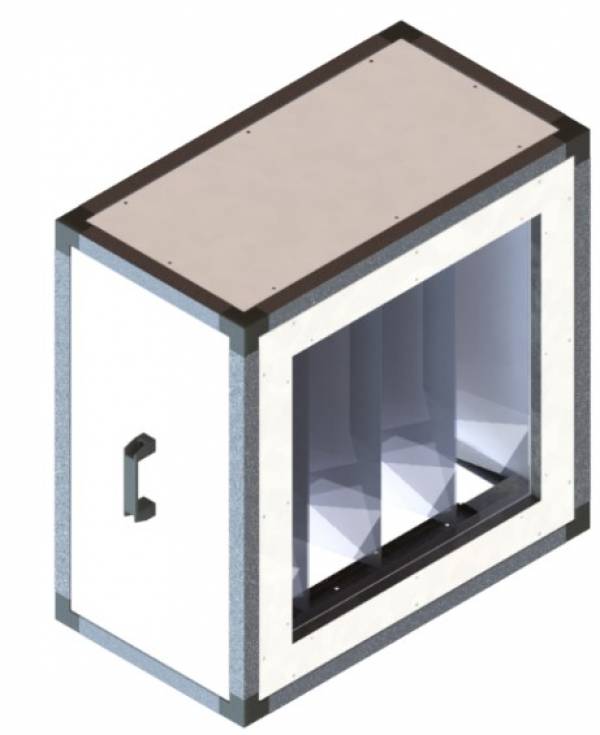
The filtration unit consists of a housing and a filter element. The filter elements are installed in guides, so they are easy to remove when replacing. The filter inserts are made in the form of bag pockets made of synthetic fiber with a cleaning class of G3, G4, F5, F7, F9. Also, the filter inserts can be made in the form of a cassette with a cleaning degree of G3 and G4, or in the form of a composite HEPA filter with a cleaning degree of E11, H13, H14.
Filters made in the form of bag pockets can have, in addition to different degrees of filtration, different lengths.
6. Silencer block
The silencer unit is designed to reduce aerodynamic noise generated by fans, air-regulating devices, as well as noise generated in air duct elements and spreading through them. Silencer sections can be installed both on the suction side and on the discharge side of the fan. The standard silencer section has a length of 500 or 1000 mm, at the customer's request it can be made in a different length.
7. Humidifier block
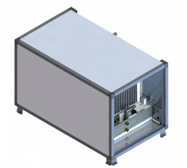
In the honeycomb humidifier block, adiabatic air humidification occurs using circulating water coming from the tray and the feed tap. The principle of operation of the honeycomb humidifier is saturation with water and cooling when passing through wet honeycombs. The humidifier is connected to a cold water supply with a pressure of 1-10 bar.
Nominal humidification efficiency: 75%
In the steam humidifier block, the process of saturating the air with moisture occurs due to the steam emitted by the humidifier. The steam is evenly supplied to the unit section through the distribution pipes. The main advantages of this type of humidification are the constant temperature of the air passing through the humidifier and the high accuracy of maintaining humidity.
Nominal humidification efficiency: 85%
The sections of the steam and adiabatic humidifiers are made of panels with an internal stainless steel coating and are equipped with a stainless steel tray.
8. Air valve
The air damper is designed to regulate the air flow passing through the ventilation unit sections. The damper is made of aluminum profiles. It consists of a housing and rotating blades, support bearings, seals and an electric drive. The blades are made of special shaped profiles. A drive is used to rotate the blades. The sealing of the blades at the joints is provided by a rubber profile. By default, the valves are equipped with TS05-230 (with a return spring) or Luftberg DA__N220 (without a return spring) drives. A different drive can be installed upon request. The electrical connection of the electromechanical drive is made in accordance with the diagram attached to the ventilation unit.
9. Flexible insert
Flexible inserts are designed to prevent the transmission of vibrations from the ventilation unit to the air ducts and are used in ventilation systems at temperatures from -50 to +80 degrees.
Inserts are made of galvanized steel and combined flexible material. The maximum width of the flexible insert is 140 mm.
The insert has a flange connection for fastening to air ducts.

